Tuesday, 12 March 2019

Understanding FPV connectors: SMA vs RP-SMA

The two types of connectors that are usually used in FPV transmitters, receivers and antennas are SMA and RP-SMA. Like cat6 connectors, the SMA and RP-SMA connectors are used for connecting coax cable and antennas.  In this article, we have provided a difference between these two types of connectors. Usually, it is difficult to distinguish between these two connectors as the gender of SMA and RP-SMA connectors are confusing.


Even the manufacturers sometimes get confused between these two types. Whenever you are buying FPV equipment with SMA connector, make sure that the description of the equipment matches with the image of the equipment. If there is any mismatch, you should ask the seller.
Difference between RP-SMA and SMA Antenna Connectors

These two types of connectors are the original ones used in FPV products. These connectors are very versatile and robust due to which they are used widely. However, these connectors are heavier as compared to others. 

SMA consists of 500+ mating cycles. These cycles are more than those of other types like MMCX and U.FL.  Almost, all the receivers use SMA or RP-SMA connectors because the weight is not a problem on receiving side.

SMA are coaxial RF connectors developed in the 1960s and it stands for Sub-Miniature Version A. Whereas, RP-SMA stands for Reverse Polarity SMA. As evident from the name, RP-SMA is a variation of the SMA connector. In these connectors, the gender of the interface is reversed.
SMA is more popular as compared to RP-SMA especially in case of a mini quad industry. The major difference between the antennas of two connectors is that an SMA antenna consists of a pin in the middle whereas the RP-SMA antenna is the exact opposite of SMA and it also has a small hole in the center.

SMA and RP-SMA Adapter

In case, if you have got the antennas of the wrong connector then you can get an adapter for it. Some adapters consist of an angle. This makes mounting of the antenna more flexible.
But you must keep in mind that by using an adapter, there is always some loss of performance. Hence, a good approach is to avoid the use of the adapter.

Changing or removing the SMA Connectors

Most of the people choose to remove or replace the connectors with some other ones or people also choose to connect a pigtail extension on the video transmitter. This is done for saving the components from breaking off.

If you want to replace RP-SMA to SMA or vice versa on a video transmitter then cut off the bulk of the connector. This can be done by using some wire cutters or Dremel cutting wheel. You can use iron for removing the remaining legs off the VTX surface. You can also do this by just using an iron without cutting anything off.

Conclusion


We hope that the article has helped you in understanding the FPV connectors. If you have any questions related to the article, please ask in the comment box below. Keep visiting our website for further information related to connectors. 

Saturday, 23 February 2019

Understanding the Significance of DisplayPort Cables

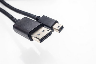
Along with the advancement in technology, the electronic components are also changing very rapidly. You may have seen many new connectors in the market. In this article, we have discussed the DisplayPort Cord which is also known as the digital display interface. This cord standard is used and approved by the well-known names in the market like Apple, HP and Dell.


DisplayPort cables are different from conventional outdoor cat6 cables as these cables are used with audio and video devices. The DisplayPort Cables have the ability to support the HD video resolutions of up to 2560 x 1600 along with 10-bit color. Many professionals are using this cord in their companies. These ports are capable of providing connections between the external as well as internal displays. Moreover, these cords can also provide displays in slim and cheap manner. In this article, we have provided the significance of display port cables.

Provides proficiency:

If you choose a good quality DisplayPort cable, then it can also drive the display panels. It has the capability of replacing LVDS (low voltage differential signaling). You do not need to have a VGA silicon and DVI controller as DisplayPort Cord can serve the purpose. Hence, in this way you can save money.

Cabling is not required in display areas or the PCs body if the internal display port wiring is used. Display Port has the ability to provide a directional channel hence the performance will also boost. It can also perform some other functions like notebook backlighting control.

Replacing DVI

DisplayPort is capable of replacing DVI on PCs and monitors. If you look at its anatomy, then you will come to know that it consists of a USB size form factor. It also contains a self-latching mechanism. The Display Port cable is much slimmer than DVI or SVGA cables.

The users want a good picture quality. There has been a lot of saturation in DVI. Moreover, it has a bandwidth of 1920x1200. Hence, it cannot be used for providing HD services. On the other hand, you can use DisplayPort cables for transmitting data up to the rates of 8.64 Gbits. Moreover, the DataPort also has an auxiliary bidirectional data channel. This channel is capable of carrying data for touch panels, webcams and microphones.

DisplayPort can be connected easily to DVI, VGA or HDMI with the help of adapters. But Display Port cannot be converted into analog television connections such as component video, and s-video. According to professionals, the future of DisplayPort is very bright. Many more exciting features can be incorporated in these cables.

However, we know that DisplayPort was launched to replace DVI, VGA and interfaces of internal LVDS. HDMI was used to overcome the limitations posed by S-Video interfaces and Component. Now the question is that which one is a better choice?


Display Port as well as HDMI both can fulfill your requirements related to video cable and adapter. Do not forget to share your valuable suggestions in the box below. You can also ask questions related to the article.

Wednesday, 20 February 2019

Understanding the Utility and Importance of Ethernet Ports

Almost all of you must have heard the term “Ethernet cables.” Usually, these cables are plugged into network equipment. In this article, instead of discussing the Ethernet cables, we will discuss the ports in which these cables are plugged in. Here, we will provide you with complete information that how these ports provide a connection between the wired network and WAN or LAN.


Have you ever seen the Ethernet connections provided at the back of your computer devices? The router consists of different Ethernet ports. These ports have the ability to handle many devices across a single network. In most of the cases, an Ethernet port takes an Ethernet Cord. The Ethernet Cord has an RJ-45 CAT6 connector. If you want to use the internet without wire, then you can get a WIFI network.

The Appearance of Ethernet Ports

Ethernet port looks almost the same as that of the traditional telephones, just a little wider than them. Ethernet Cables cannot fit into the telephone port so from there you can analyze the difference. 

Ethernet Ports of Computers

All the computers consist of Ethernet ports. With the help of these ports, you can connect your devices to the wired networks. The Ethernet port of PCs is  connected with Ethernet network adapter which is also known as Ethernet Card. The Ethernet Card is attached to the motherboard.
The laptops also have Ethernet ports which are used for connecting them with wired networks. But some laptops like MacBook air do not consist of Ethernet ports. However, you can connect the Ethernet dongle to the USB port of a laptop.

How to handle Ethernet Port Issues?

If you are facing the issues in your internet connectivity, then first you must look at your Ethernet port. There is a possibility that the port is unplugged due to which you are facing internet issues. In such case, the computer also shows notifications like “the network cable is unplugged.” There is also a possibility that the issue is due to a corrupt or outdated network card. In that case, you can install a network driver by using the driver updater tool which is free.

Uses of Ethernet ports

Below, we have mentioned some of the uses of Ethernet ports:

1.      Ethernet Ports used in Routers

Usually, the Ethernet ports are used in broadband routers. It allows various wired computers to connect with the internet and other devices which are in the network. In some case, the uplink ports are also used. The uplink ports are a type of Ethernet Jack which is used for connecting to a broadband modem.

2.      Ethernet Ports used in different Electronic devices

Ethernet ports are used in many electronic devices like video game consoles, TVs, recorders etc.  Google Chromecast is the latest one. You can buy an Ethernet adapter for it.

This is some basic information related to Ethernet ports. We hope that this article will help you in understanding Ethernet ports. If you have any question related to the article, please feel free to ask in the comment box below:

Wednesday, 6 February 2019

How a Bi-Directional Amplifier Improves In-Building Communication


You may have heard of bi-directional amplifiers while looking for an improvement in the in-building communication. The dead zones and poor coverage cannot only cause frustration, but it also reduces productivity and efficiency of work. You can greatly improve your in-building communication by using bi-directional amplifiers or BDA.


BDA is an important communication tool that boosts the signal level to eliminate the dead zone and spotty reception of signals. This amplifier is usually used in large buildings like campuses, hospitals, hotels, or manufacturing plants for improving communication.

The major task of this amplifier is to locate the signal, boost it to the required level and then distribute it throughout the network. In this article, we have explained how BDA improves the communication within large buildings. Let’s dig out the topic in detail!
How BDA works?

Locating the Signal: The first step of the BDA’s process is to locate the signal and then capture it. The signal is usually received from the antenna that is mounted on the roof of the building.

Amplifying the Weak Signal: Once the signal has been located by the BDA, the next step is its amplification. The amplifier will then amplify the weak signal so that the signal can travel properly throughout the network.

Redistribution of the Signal: The next step is to redistribute the amplified signal throughout the building. This process depends on the installation of the BDA. If BDA is placed at a perfect location then it can receive more signals transmitted by the antenna; hence, the amplification process will be more efficient. Therefore, it should be placed strategically so that it can receive the best signal possible. The amplified signals have the ability to provide reliable coverage even when obstructed inside the building.

Setting Up BDA: As mentioned earlier, it is very important to install BDA at the correct location for its proper working. The best way is to take help from an experienced solutions provider who can analyze your structure and determine the best location(s) to place the BDA(s).  The installation of BDA includes two steps: strategy and then implementation. So, it is very important to have a correct strategy before installing BDA. We will not recommend you install BDA on your own as it is quite risky. The wrong placement of BDA can result in inefficiency of equipment.

BDAs are very complex devices; hence, they require expert attention. You can get help from the experts who have an involvement in the engineering, design, analysis, and installation of such system. BDAs have various applications, though; these devices can fulfill the specific needs of your organization. BDA’s can be used in hospitals, manufacturing plants, campuses for schools, universities, shopping centers and malls, airports, convention centers, stadiums, and arenas etc.

We hope that this article will help you to improve communication within your organization. Visit verified stores for variety of amplifiers. You can also get Trellisware amplifier for boosting the signals within the building. If you have any questions related to the article, feel free to ask in the comment box below:


Tuesday, 15 January 2019

What is a Coax Cable?


All of you may have seen the coaxial cables in your homes. But have you ever wondered that what is the use of this cable and how is it different from other cables?
Coaxial cables are used around the world for delivering voice, video and data. However, coaxial cable has some limitations due to which it has been widely replaced by fibre optics or wireless signals in the recent years but even then it is not possible to eliminate the use of coaxial cable. The reason of its success is its shielded design. The shielded design allows the copper core of the cable to transmit the data at a faster pace without getting damaged from environmental factors. 
The coax cable comes in three common sizes i.e., RG-6, RG-11 and RG-59. For connecting coaxial cables, the F-style connectors are the most common ones. However, some systems also use N-type connectors. There are many types of F-type connectors for RG-6 cables i.e.
·         Compression connectors
·         Screw-on connectors
·         Crimp-style connectors

What is coaxial cable?


In coaxial cable the inner conductor is surrounded by an insulating layer which is then surrounded by a conductive shielding. Most of the coaxial cables also contain an insulating outer jacket. The electrical signal flows through the core of the cable which is usually made up of copper conductor. Below is the detailed construction of a coaxial cable:

  1. Center conductor is made up of copper-clad steel.
  2. Center conductor bond is a clean stripping polymer which is used to block the moisture.
  3. The dielectric layer is made up of polyethylene which is used for providing mechanical stability. It is a closed cell foam with high VP.
  4. The first outer conductor is shielded with an aluminum-polymer-aluminum tape and is bonded to the dielectric core.
  5. The second outer conductor is an additional aluminum-polymer-aluminum tape which is used in tri-shield and quad-shield constructions. This outer conductor is used to further enhance HF shield isolation in case of cable bending.
  6. The third outer conductor is also an additional aluminum-polymer-aluminum tape. This layer is also used in tri-shield and quad-shield constructions. The main purpose of third outer conductor is same as the second one. It enhances the HF shield isolation.
  7. The fourth outer conductor is the last outer conductor. It is an additional 34 or 36 AWG aluminum braid which is used in quad-shield constructions. The purpose of this conductor is to improve LF shield isolation in environments where the RF noise is at extreme level.
  8. Corrosion resistant protectant is of two types: Indoor and aerial - it is a non-drip material which is designed to eradicate the migration of moisture into construction of cable.Underground - this flowing compound can seal small jacket ruptures.
  9. The outer jacket is UV stable which is made up of polyethylene (PE) or flame retardant polyvinyl chloride (PVC). This outer jacket is used for the protection of the cable.
  10. The last part is an integral messenger which is a galvanized, carbon steel wire support member. It is attached to the cable by a separable web.


We hope that this article will help you to get a better understanding of the coaxial cables. Stay tuned to our website for more information about communication hardware.

The Role of Coaxial Cable in Broadband Networks

The cable operators, telephone companies, and internet providers use coaxial cables for delivering data, video, and voice communications to customers. This technology is in use since the early 20th century and it provides reliable communication services.

In broadband communication, the data, voice and video are converged on a single infrastructure for better use of bandwidth.  Usually, optical fiber is used as for transporting the signals over larger distances and coaxial cable is deployed for distributing the signal across the network. Hence, before deploying the coaxial cable, it is very important for engineers to understand its characteristics. In this article, we have explained the basic role of coaxial cable in broadband networks.

RF Transmission


The cables are classified into different categories. The coaxcable falls into "RF-transmission line" category because it can transmit the radio-frequency (RF) signals efficiently. Due to its physical characteristics, it transports the RF signals rather than radiating them. The physical characteristics of this cable depend on the bandwidth; the greater the bandwidth carried by this cable, the more critical the physical characteristics. Hence, it is necessary to properly install the cables and connectors for better performance.

The attenuation of a coaxial cable can be determined by three major factors i.e., resistance, dielectric material, and radiation. The greatest amount of attenuation per unit length in the coaxial cable is produced by the resistance. Resistance depends on the cable materials, frequency of the transported signal, diameter of the conductors, and ambient temperature.

The attenuation is not greatly affected by cable dielectric. The major use of dielectric material is to maintain the spacing between the shield and center conductor. A small amount of signal energy dissipates in the dielectric as this material is not a perfect insulator. For reducing the attenuation in coaxial cable, dielectric materials with better insulating properties can be used.

Almost all the cables face some attenuation due to radiation. It is not possible achieve perfect cable dimensions hence, a small amount of energy leakage can occur due to the symmetry of the cables. However, it is very important that the RF signals do not escape from the coaxial cable otherwise these signals can interrupt with the wireless services.

Moreover, it is very important that the impedance of the transmission medium matches with the impedance of the devices used in the system. If there is a mismatching between the two then it can lead to transmission problems.

The Right Connections


Another challenge is to make the right connections in order to maintain network performance. The connector must be capable of maintaining RF characteristics as well as the characteristic impedance of the cable. The connectors that are used for connecting the rigid coaxial cable are usually a three-piece design. For flexible coaxial cables, usually, F-type connectors are used which is normally a one-piece connector.

Hence, by making the right connections and reducing the losses, rf signals can be transmitted successfully across the broadband networks by using coaxial cable. If you have any question related to the article, please feel free to ask in the comment box below: